Ac Voltmeter Wiring Diagram from wiringdiagramall.blogspot.com
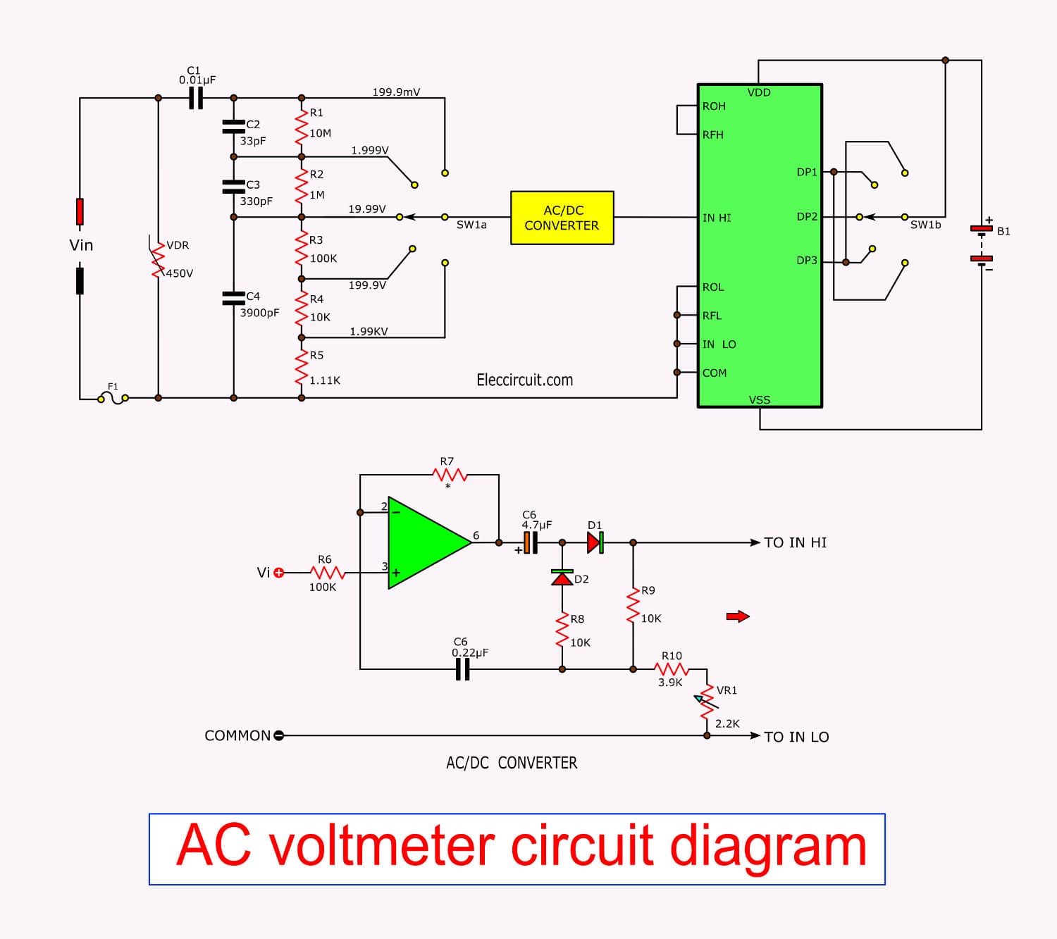
Voltmeter In A Circuit Diagram. The instrument which measures the voltage or potential difference in volts is known as the voltmeter. So, the circuit diagram of ac voltmeter using full wave rectifier will look like as shown in below figure.
The instrument which measures the voltage or potential difference in volts is known as the voltmeter. Alternatively, radio frequency (rf) voltage can also be. The vacuum tube diode connects in series with resistance raises the strength of the weak signal. Full wave rectifier and dc voltmeter. A circuit diagram is also known as an electrical diagram, elementary diagram or electronic schematic. In this case average current through the meter will be v rms / 1.11r. Analog voltmeters move a pointer across a scale in proportion to the voltage measured and can be built from a galvanometer and series resistor. A voltage divider with resistance values of 250 mω and 9.615 mω will divide 24 volts into portions of 23.1111 volts and 0.8889 volts, respectively. The circuit of the diode voltmeter consists the pmmc meter, load resistor, vacuum tube diode.
The Circuits Described Here Do Not Represent Those Of Any Specific Make Of A Digital Voltmeter.
The range could be properly broadened or hardened easily by changing the value of the 1m resistor placed in series with the input terminal. Rather than using the absolute analog ways of finding out the voltages, the. A voltage divider with resistance values of 250 mω and 9.615 mω will divide 24 volts into portions of 23.1111 volts and 0.8889 volts, respectively. A voltmeter is connected in parallel to a circuit element because when connected in parallel it draws least current from the main current. In figure below is icl7107/7106 pinout. Circuit symbols are used in circuit schematic diagrams which show how a circuit is connected together electrically. Because of the vacuum tube, the system becomes more sensitive than the normal voltmeter. A voltmeter is a high resistance galvanometer used to measure potential difference. The circuit diagram of multi range dc voltmeter is shown in below figure.
In This Case Average Current Through The Meter Will Be V Rms / 1.11R.
This ic is a 40 pin model. Referring to the circuit diagram below, the unit is a full fledged digital voltmeter circuit which can be used for measuring direct voltages right from zero to 199 volts. Voltmeter which is also known as voltage meter is an instrument that measures the voltage or potential difference among two points of an electronic or electrical circuit. So, the circuit diagram of ac voltmeter using full wave rectifier will look like as shown in below figure. The voltmeter is also a. Digital electronic voltmeter circuit diagram. Digital voltmeter circuit design using 8051 microcontroller. The above block diagram consists of two blocks: We can choose the desired range of voltages by connecting the switch s to the respective multiplier resistor.
A Circuit Diagram Is A Simplified Representation Of The Components Of An Electrical Circuit Using Either The Images Of The Distinct Parts Or Standard Symbols.
In the above circuit, analog to digital converter ic data bits are connected to the port2. Talking about the circuit diagram below, the unit is a complete fledged digital voltmeter circuit that are available for calculating direct voltages starting from zero to 199 volts. It measures voltage from 0.00v to 99.9v. Full wave rectifier and dc voltmeter. Digital led voltmeter circuit specifications: Usually, the voltmeter is used for alternating current (ac) circuits or direct current (dc) circuits. Needless to say, the ic l7107 can be also rigged into a simple yet accurate panel digital voltmeter circuit, which is what we are presently interested in. Working principle of digital voltmeters: A voltmeter is an instrument used for measuring electric potential difference between two points in an electric circuit.it is connected in parallel.it usually has a high resistance so that it takes negligible current from the circuit.
The Circuit Diagram Of The Diode Vacuum Tube Voltmeter Is.
An ideal voltmeter has infinite resistance. The vacuum tube diode connects in series with resistance raises the strength of the weak signal. Lcd data pins are connected to the potr3 of controller and control pins rs and. Ammeter and voltmeter the ammeter is an electronic measuring device that measures the electrical current in the circuit. Main advantages associated with these voltmeters are that they are simple in construction, have high input impedance, low power consumption and. Beside that, a cathode follower in a vom of this circuit is the 2n3819. The circuit of the diode voltmeter consists the pmmc meter, load resistor, vacuum tube diode. The instrument which measures the voltage or potential difference in volts is known as the voltmeter. The deflection of the pointer is directly.


Post a Comment
Post a Comment